 Speedy UK Deliveries
 100% SECURE PAYMENT
 VOLUME DISCOUNTS
 Contact us
Speedy UK Deliveries100% SECURE PAYMENTVOLUME DISCOUNTSContact us
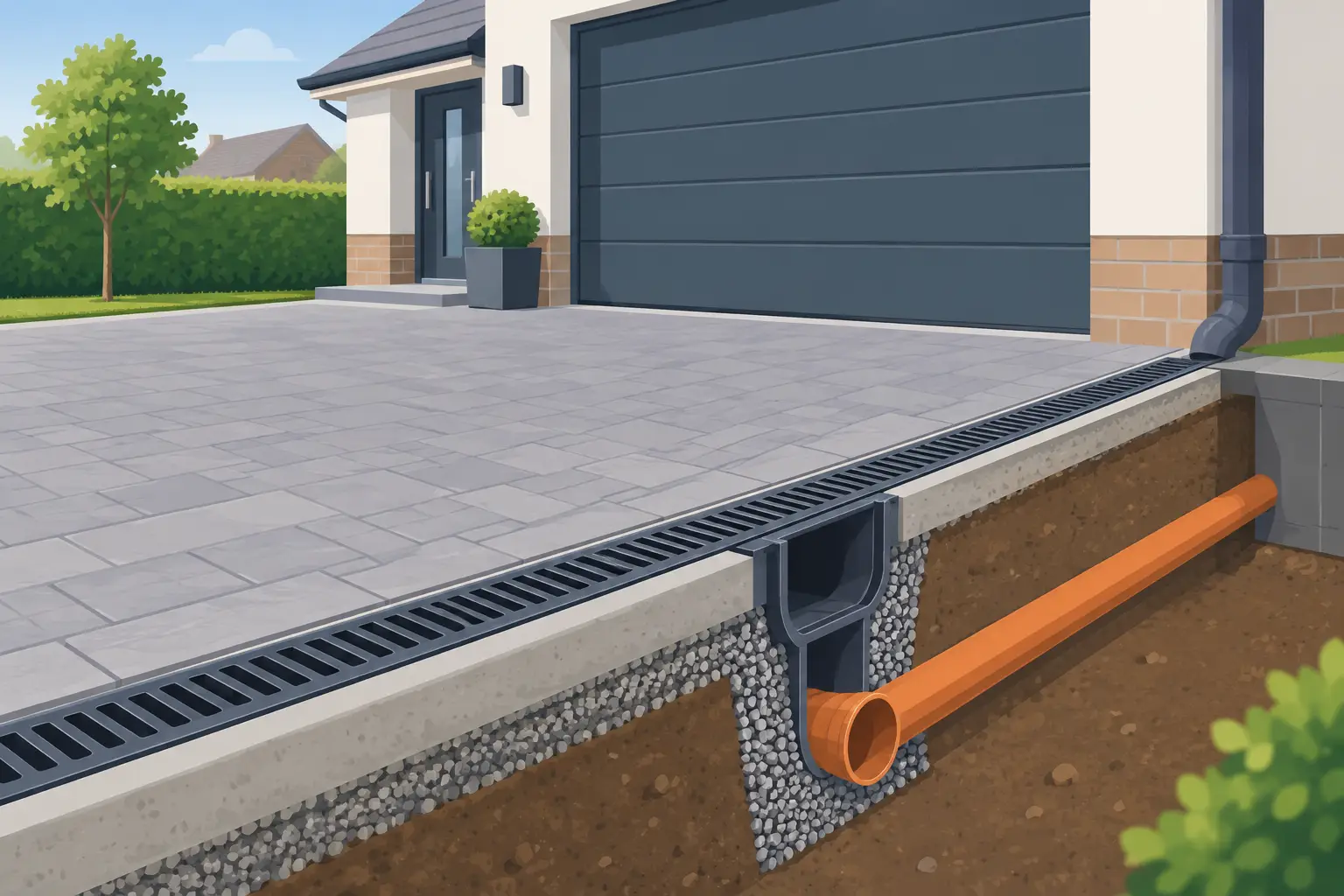
A driveway that holds water outside a garage, front door or bay window is not simply inconvenient. Repeated ponding can undermine paving, carry silt into gullies and direct water towards the property. This driveway drainage installation example shows how a typical domestic system can collect runoff at the low point, transfer it through underground pipework and discharge it to a suitable on-site drainage point.
The exact design depends on ground conditions, available levels, vehicle loading and the legal drainage route. Treat the example as a practical starting point, not a substitute for a site survey where water has caused persistent flooding or where a connection to a sewer is proposed.
Consider a 6 m by 5 m block-paved driveway sloping towards an integral garage. Without a drainage channel, rainwater runs directly at the garage threshold. The proposed arrangement places a linear channel drain across the full width of the entrance, roughly 300 mm in front of the garage door. The paved driveway falls towards the channel, while the channel outlet connects to 110 mm underground drainage pipe.
From the outlet, the pipe runs away from the building to an inspection chamber and then to a soakaway crate system located in a suitable area of the garden. The soakaway is wrapped in geotextile membrane and positioned clear of foundations, boundaries and services, subject to the site design. Its job is to allow collected surface water to disperse into suitable ground rather than return across the drive.
This arrangement separates driveway water from foul drainage. Surface water must not be connected to a foul sewer. If a surface-water sewer connection is being considered instead of a soakaway, check the permissions and requirements with the relevant sewerage provider and local authority before work starts.
The channel, pipe and soakaway only work if the levels work. Set the finished level at the garage entrance first, then establish the paving fall back from that point. A fall of around 1:80 is often used for hard landscaping, but the finished surface and channel manufacturer’s requirements should guide the final design.
The channel should be the low point, not a raised strip that water has to cross. Allow for the depth of the channel body, the bedding concrete, the outlet and the underground pipe when calculating excavation depth. It is common to find that a driveway looks level at surface level but leaves too little depth for a pipe to run with an adequate gradient.
For a short domestic run, 110 mm underground drainage pipe is normally a practical choice where it connects to a channel outlet designed for that diameter. Maintain a consistent fall towards the discharge point. Avoid unnecessary bends and reverse falls, as both encourage standing water and make future rodding harder.
The grate may be the visible part of the system, but the channel body and its bedding take the real load. A driveway used by cars and light vans needs a channel drainage system suitable for the expected wheel loading. Load classes should be selected to the application, not just on price or grate appearance.
For many domestic drives, B125-rated channel drainage is a common choice. Heavier vehicles, shared access roads or areas subject to frequent delivery traffic may require a higher classification. Check the manufacturer’s stated application, particularly where a wheel may repeatedly pass over the same channel section.
The channel run also needs compatible end caps, an outlet and, where appropriate, a silt trap. A trapped outlet or accessible chamber can reduce the amount of debris entering the pipework. This is useful beneath trees or on drives where grit and leaves regularly wash down with rainwater.
Mark the line of the channel and identify known utility routes before excavating. The trench should be wide enough to allow concrete bedding and haunching on both sides of the channel. Do not install a driveway channel directly on loose sub-base, soil or sand bedding. Vehicle movement can crack joints, distort the fall and leave the grate sitting below the surrounding paving.
Install the channel sections from the outlet end where the system design requires it. Most channel systems use a clear direction of flow, and the outlet position should be agreed before the run is bedded. Keep the protective grate or cover in place during surrounding concrete work where supplied, so the channel body stays correctly shaped and debris does not enter the run.
Bed the channel on concrete and provide concrete haunching to the manufacturer’s depth and width. Bring the finished paving level fractionally above the grate where appropriate, so tyres do not catch an edge and water naturally enters the channel. Keep mortar, concrete slurry and paving jointing material out of the channel during installation.
Excavate the pipe trench from the outlet to the inspection chamber or soakaway. Lay 110 mm pipe on a prepared granular bed, maintaining the planned fall. Use compatible underground drainage bends, couplers and seals throughout. A chamber at a change of direction, junction or accessible point makes cleaning and inspection considerably easier than relying on a long buried pipe run with no access.
Before backfilling, run water through the channel. Watch for slow sections, leaking joints and water sitting at the outlet. It is far cheaper to correct a low joint or reversed section before the driveway sub-base and paving are reinstated.
A soakaway is not just a hole filled with gravel. Its size must reflect the area draining to it, the expected rainfall and, crucially, the ground’s ability to accept water. A percolation test is normally required to establish whether infiltration is viable and to size the system in line with the relevant drainage guidance, including BRE 365 principles.
Soakaway crates offer a high void ratio and a predictable storage volume compared with loose rubble. Wrap the crates in the correct geotextile membrane to keep surrounding soil out while allowing water to pass through. Use an impermeable geomembrane only where the design calls for water storage or attenuation rather than infiltration.
Keep the soakaway away from buildings and consider tree roots, neighbouring land, slopes, wells and buried services. Clay-heavy ground, high groundwater or a restricted garden may make a soakaway unsuitable. In those cases, a designed surface-water connection, attenuation system or other approved drainage route may be needed.
Perforated land drainage pipe is not a replacement for a sealed surface-water pipe between the channel and soakaway. Land drain is intended to collect groundwater from surrounding soil; driveway runoff needs controlled conveyance to the intended discharge point.
For a straightforward domestic installation, the main materials usually include:
Buying the pipework, fittings, channel components and soakaway materials as a compatible system avoids delays caused by mismatched outlets and diameters. Speedy Plastics supplies drainage and water-management products for domestic and trade installations, with clear sizing across underground drainage, channel drainage and soakaway components.
Do not assume the job is complete once the water disappears from the channel. Check that the grate is secure, the paving falls cleanly to the drain and the channel has no concrete or jointing residue. Flush the system with a hose and inspect the chamber. Water should move through the pipe without backing up at the outlet.
Keep the channel clear after installation. Lift the grates periodically, remove leaves and silt, and check the accessible chamber after heavy rainfall. A correctly specified system still needs basic maintenance, especially on drives below overhanging trees.
The best driveway drainage installation is the one planned from the finished levels backwards. Set the fall, confirm the lawful discharge route, choose components that match and test the pipework before the surface is laid. That approach protects the driveway, the building and the time spent putting both in place.









 Sign in
