Speedy UK Deliveries
 100% SECURE PAYMENT
 VOLUME DISCOUNTS
 Contact us
Speedy UK Deliveries100% SECURE PAYMENTVOLUME DISCOUNTSContact us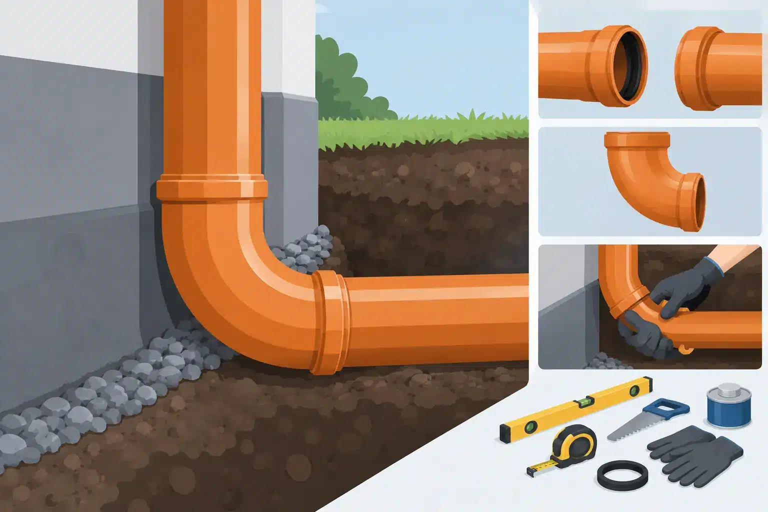
A 160mm drainage run can look right from above and still cause trouble underground if a bend is forced into place, laid against the fall or left without proper support. To install 160mm drainage bends correctly, treat the bend as part of the full pipe system, not simply a fitting that turns the line. Correct alignment, clean seals, suitable bedding and accessible rodding points all matter once the trench is backfilled.
160mm underground drainage is commonly selected where a larger-capacity run is required, including commercial premises, agricultural buildings, multi-property connections and sites with substantial surface-water flows. It is also used where the drainage design, existing connection or local authority specification calls for this pipe size. The fittings must match the pipe system in both diameter and material specification.
Start with the drainage drawing or establish the route from the discharge point to the inspection chamber, manhole, gully or approved connection. Mark every change in direction and identify where access will be needed for future cleaning. A bend may shorten the route, but a poorly positioned sharp turn can make rodding more difficult and increase the chance of debris settling in the line.
Choose the bend angle to suit the route rather than using the tightest turn available by default. Shallow 15-degree, 30-degree and 45-degree bends are generally preferable for gradual directional changes. Where a larger turn is needed, two swept bends with a short straight between them can provide a more serviceable route than one abrupt change. The best arrangement depends on space, the pipe gradient and the access available either side of the turn.
Confirm whether the run carries foul water, surface water or another specified flow. These systems must not be connected together unless the drainage design and local arrangements permit it. Check the required fall before setting out. A pipe laid too flat can allow solids to settle, while an excessive fall may leave solids behind as water outruns them. The correct gradient depends on the system design and discharge type, so follow the drawings and relevant Building Regulations guidance rather than relying on a one-size-fits-all figure.
Use 160mm underground drainage bends made for the same nominal pipe size and compatible socket arrangement as the pipe. Underground drainage systems are commonly manufactured in PVC-U, but compatibility is about more than colour or outside appearance. Check the fitting profile, seal type and stated application before ordering.
A standard socketed bend normally uses an elastomeric ring seal to create a flexible, watertight joint. This allows a small amount of movement in the ground while keeping the connection sealed. Do not confuse underground drainage fittings with soil-pipe fittings or use an improvised adaptor simply because the diameters appear close. A correct fitting is cheaper than reopening a trench to repair a leaking joint.
For a typical installation, the required materials include 160mm pipe, the selected bends, compatible couplers where needed, inspection chambers or access fittings, granular bedding material and suitable backfill. You may also need a branch, reducer, gully connection, chamber base or pipe adaptor depending on the layout. Ordering all connected components together helps avoid delays once excavation has started.
Excavate the trench wide enough to allow the pipe and bend to be lowered without scraping the trench walls or disturbing the intended line. Remove loose soil, large stones, brick fragments and any hard projections from the base. These can create point loads that distort the pipe or fitting after backfilling.
Lay an even bed of suitable granular material and shape it to support the pipe continuously. The bend needs the same care as the straight lengths. Do not leave the body of the bend suspended between two supported pipe ends, and do not use pieces of timber, broken blocks or loose spoil to pack underneath it. Support should be firm and even along the barrel so the joint is not put under stress.
Set levels with a laser level, pipe laser or other reliable method. A string line can help with the route, but it is not a substitute for checking the actual invert levels. Check the fall before installing each section, especially where bends bring the pipe closer to a chamber or where the trench changes depth.
Ground conditions and loading affect trench details. A shallow domestic run in soft garden ground is different from drainage beneath a driveway, access road or area used by vehicles. Where pipes pass beneath trafficked ground, are installed at unusual depths or cross unstable ground, follow the project specification and seek suitable engineering advice. The bedding and surround are part of the installation, not an optional extra.
Before making a joint, inspect the socket, rubber seal and plain spigot end. The seal should sit evenly in its retaining groove, with no twists, cuts, grit or damage. Clean both joint surfaces thoroughly. Even a small piece of stone trapped under the seal can prevent full engagement and create a path for water or roots.
Check the insertion depth by using the manufacturer’s witness mark if present, or make a temporary mark on the pipe spigot after a dry fit. This helps you confirm that the pipe has entered the socket fully without pushing it so far that the joint has no allowance for normal movement. Follow the fitting manufacturer’s instructions where expansion gaps or insertion marks are specified.
Apply an approved water-based joint lubricant to the pipe spigot and, where directed, the seal. Do not use oil, grease, washing-up liquid or petroleum-based products. These may damage the seal, attract dirt or make the joint unreliable over time.
Align the pipe and bend squarely before pushing them together. The pipe should enter straight into the socket – forcing it in at an angle can roll or dislodge the rubber ring. Use controlled hand pressure or appropriate installation equipment for larger sections. Avoid striking the fitting directly with a hammer. If resistance feels excessive, stop, separate the joint and check the seal, cleanliness and alignment.
Once the bend is connected, recheck line and level immediately. A bend can rotate slightly while the next length is being fitted, particularly in a wide trench or loose bedding. Keep socket directions consistent with the intended flow and maintenance arrangement. Then lightly support the fitting in place with selected granular material before moving on.
Drainage is easier to maintain when access has been planned at the installation stage. Direction changes, junctions, changes in gradient and long pipe runs are common places where inspection chambers, rodding eyes or other approved access points may be required. The exact arrangement should follow the drainage design and Building Regulations guidance for the property.
Do not bury a complex sequence of bends with no route for rodding simply because the system passes an initial water test. Tree roots, silt, wipes and building debris do not announce themselves on installation day. A chamber positioned at a significant change of direction may cost more initially, but it can prevent a disruptive excavation later.
Where a 160mm line connects to an existing chamber or pipework of another size, use a purpose-made connector or adaptor. Do not rely on sealant, foam or mortar to make up a diameter mismatch. The connection must be mechanically sound, watertight and suitable for the ground conditions.
Test the run while all joints remain visible. Depending on the job specification, this may involve a water test, air test, visual check or a combination of methods. Check that water passes freely through the bend, that there is no standing water at a joint and that no seal has been displaced during assembly.
Inspect the route from both directions where possible. Look for a dip at the bend, a reverse fall near a chamber or a joint that has not reached its insertion mark. Correcting any of these faults before backfill is straightforward. Correcting them after landscaping, paving or a concrete slab has been completed is not.
Once the installation has been checked, place selected granular surround evenly around the pipe and bend. Build it up at both sides in layers so the fitting does not shift or twist. Compact carefully by hand around the pipe zone as appropriate for the material and specification, taking care not to damage the pipework.
Continue the surround to the required level before placing excavated backfill. Keep sharp stones, rubble and large clods away from the immediate pipe zone. Backfill should be placed and compacted in controlled layers, particularly under paved or trafficked areas where future settlement can damage both the surface and the drainage below.
For trade and DIY projects alike, the reliable approach is simple: use compatible 160mm fittings, maintain the designed fall, support every bend properly and leave sensible access for maintenance. Speedy Plastics supplies 160mm underground drainage pipework and fittings for customers who need a dependable, trade-ready system at competitive prices. Get the route right before the trench is closed, and the drainage should stay out of sight for the right reasons.